|
You are reading the older HTML site
Positive Feedback ISSUE
19
Lynn Olson's 2004
European Triode Festival Presentation Re-printed courtesy of PFO Senior Assistant Editor Lynn Olson, and are re-printed from the Nutshell Hi-Fi site at http://www.nutshellhifi.com/library/ETF.html.
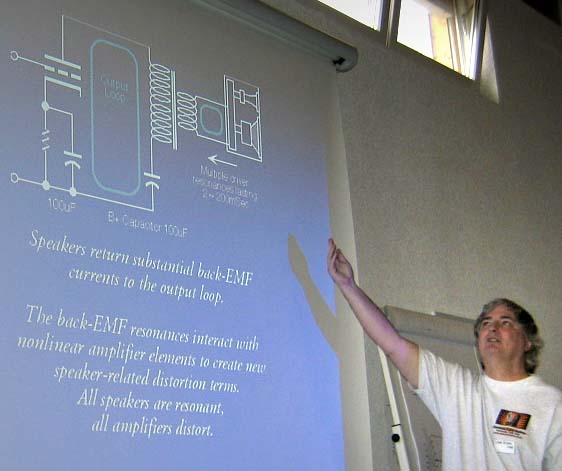
Here's a brief summary of the opening presentation given at the 2004 European Triode Festival, which builds on a previous presentation given at the Bay Area Tube Fest as well as additional new research by John Atwood, Gary Pimm, and Mark Kelly. Since it is easier to measure voltages than current, many engineers and audiophiles only think of the so-called "signal path" within an amplifier, where measurable voltages above ground appear. All the sloppy, hard-to-measure currents are usually ignored, especially currents that return along the ground path. But in reality, without current, there is no amplification, and certainly no power to drive a loudspeaker. And current, as you remember from grade school physics class, always requires a loop in order to flow and complete a circuit. The true signal path in a functioning amplifier is a complete current loop that connects sender and receiver. The simplest possible amplifier has two separate current loops; one at the input, and one at the output.
A vacuum-tube has a differential input (grid and cathode) and a differential output (plate and cathode). There are differing impedances for the respective nodes, but the tube neither knows nor cares about chassis ground, nor input grounds. Grounds are nothing more than a convenient low-impedance summing node for the circuit designer; the tube itself does not require any ground at all, since it only senses differential inputs and also has a differential output. These days passive components are not automatically assumed to be sonically invisible, so you have count up every part in this loop to understand where coloration may be coming from. In a conventional SE amplifier, for example, the output loop goes from plate -> OPT -> PS cap -> cathode-bypass cap -> return to cathode. Every part in this loop is in the direct signal path, and adds coloration to the sound. In many circuits the power supply B+ filter cap and cathode-bypass cap are electrolytics of opposite polarity, differing values, and different voltage-breakdown rating. What chance is there that cap-coloration will somehow magically disappear from this series-string of caps? The same analysis applies to the input side - even though currents are very low, the differential input of the vacuum-tube is still affected by all the parts in series between the tube and source components. The tube doesn't amplify the grid signal—it amplifies the potential voltage difference between the grid and the cathode, so the cathode-side circuit matters just as much as the grid circuit. The output loop between the plate and cathode carry large audio-frequency currents, while the input loop between the grid and the cathode carry very small (but not zero!) audio-frequency currents. Both loops are sensitive to the parts that are used in the loop - the triode, transformer, capacitors, and very possibly, the wire itself. Keeping in mind the current loop, consider the following topologies. Although they may seem to have redundant return paths, remember, the majority of the current will always flow along the low-impedance path. This is one of the primary advantages of the "alternative" topologies shown below; the audio-frequency (AC) currents are no longer forced through the low-quality power-supply B+ capacitor, leaving it perform the much simpler task of filtering ripple from the power supply.
All PP or differential amplifiers are really two amplifiers operating in parallel: a perfectly balanced PP amp, and a secondary SE amplifier running 26-30dB down from the main PP amplifier. This secondary, "shadow," amplifier is the sum of all imbalance terms in the tubes and transformer primary, typically 2~5%. You can try various nulling schemes, but this makes the problem worse, not better, because as the residual approaches zero, you start to see frequency and phase-dependent terms appear. In other words, the null will only be at one frequency and power level, and will skip around on both sides of the null under real-world conditions.
Deliberately increasing imbalance, such as 20-30%, using dissimilar tubes or unequal grid feeds, seems to have the worst of both SE and PP worlds, maximizing the coloration of each type. The best approach, sonically and electrically, is the simplest: let the tubes find their own degree of imbalance, and design the circuit around that. Functionally, assume the top tube is running at 105% gain, while the lower tube is running at 100% gain. The net overall gain is 102%, and the gain of the imbalance signal is 5%. The imbalance signal has almost no effect on overall gain or frequency response, but is responsible for all of the even-order distortion and power-supply noise getting into the circuit. The imbalance audio-frequency currents flow through the cathode circuit in the same way as a SE amplifier, favoring whichever tube has the most gain at the moment.
The following two circuits are sometimes called "forced balance," since both tubes deliver the same net gain. This isn't as surprising as it sounds; the tubes are in series, after all, so the gain is simply the instantaneous sum of the two. This has certain consequences; when one tube current-limits or clips, the amplifier stops amplifying, just like removing a light from a series-string Christmas light turns off the whole string. By contrast, a conventional Class A PP amplifier (as shown in the first set of drawings) operates in parallel. When one tube current-limits or clips, the other tube just turns on harder to compensate. Conventional Class A PP amplifiers are functionally in parallel, while forced-balance differential amplifiers are in series. This has implications for clipping, current overload, even the distribution of distortion harmonics. Two tubes operating in series function somewhat differently than tubes in parallel, and produce different types of distortion. The series circuit will clip sooner, since it cuts off on both sides of the waveform (a SE circuit only cuts off on one side of the waveform, while a conventional Class A PP circuit allows the "on" tube to take over from the "off" tube). Interestingly, it is possible to make a transitional class of amplifier by the simple expedient of inserting a simple shunt circuit between the paired cathodes and the center-tap on the output transformer: a 10 to 40uF audio-grade cap in series with a variable resistor (approx. 1K is sufficient). For some tubes (indirect-heated cathode types) the lowest distortion null is between 50 and 150 ohms, while direct-heated types favor a value of zero ohms (conventional Class A PP circuit). The lowest-distortion shunt resistor appears to be a function of the tube's distortion spectra; tube with the lowest amount of upper harmonics favor a value of zero ohms in the shunt circuit, while tubes that have a bit more upper-harmonic favor something around 100 ohms or more.
Text and Pictures © Lynn Olson 2004, except where noted.
|