|
You are reading the older HTML site Positive Feedback ISSUE may/june 2007
The Development of the Continuously
Loaded Conductors
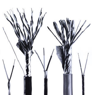
Historically signal cable development began with telephone lines. The key to cable quality lies in the relationship of their conductive and non-conductive materials (conductors and dielectrics). Low and high frequency cables have their own unique sets of problems. High frequency cables with a small dynamic range are concerned with cable rise time, digital and large dynamic range audio cables are more concerned with dielectric relaxation time or decay. Telegraph signals in the 1800s were virtually identical to modern digital signals but a bit slower. They used simple wire leads (open wire); first a single wire and ground return; and then open wire pairs as grounds degraded. Transmission distance was extended by simply increasing voltage and repeater sensitivity. High battery force (low impedance); low wire resistance (low transfer impedance); and sensitive relays (high impedance) could deliver a readable pulse 200 miles on an 8-gauge wire. This was a very efficient rising impedance system. By 1870, Webs of noisy, exposed wire had hit their limits. Telephones needed quiet low distortion signals for voice intelligibility. Existing cables using, paraffin impregnated cotton, gutta percha (like latex), rubber and other insulations were inadequate, Line resonance distorted signals. Voices were unrecognizable, muffled, hollow, echoic etc. Transmission distances were limited. But knowledge was growing rapidly. In 1873, James Maxwell reduced theory to four fundamental laws that explained known electric and magnetic phenomena. By 1890 the better dielectric qualities of dry paper insulated, 18 gauge shielded cables improved sound quality and transmission distance, but after this addition cable improved little for decades. It was known at the time that the cable problems related mostly to dielectric properties, conductor propagation speed, and resonance. Compared to open wire, cables were inefficient and signal quality was poor. Signals travel at light speed on open wire but slow considerably in cables as faster propagating conductors are forced to charge dielectric material. The energy stored and transferred at different time constants in cable conductors and dielectrics fuels a complex kinetic resonator. The solution at the time was to place a coil of wire (load coil) in series with the cable conductor at intervals to slow conductor speed. The load coils placed in series with cable conductors added physical and electrical length to the conductor, reducing resonance and doubling transmission distance by slowing the conductor to match dielectrics. A patent for the coil was issued to Michael Pupin in 1904, and AT&T paid him generously for its use. This deceptively simple coil of wire was a pivotal invention; it saved AT&T hundreds of millions of dollars and made cable a practical transmission medium. The load coils combined with a 600 ohm matched impedance lines traded bandwidth and dynamic range for distance and voice quality and greatly reduced cable resonance. 600 ohm lines can be visualized as a lossy set of mirrors; problems in one half are mirrored and reflected to the other. They to reduce cable resonance but lose dynamic range, bandwidth, and 50% of the signal in the process. By 1940s the focus was on compensating for cable problems and audio frequency cable development had virtually stopped; the loaded 600 ohm lines prevailed. Maxwell's equations became "Lumped and Distributed constants", analogue models were created to simply design and plastic dielectric was developed. But the cable itself had changed little since the 1890s. This is still "state of the art" for direct audio transmission over telephone cable. The solution to telephone audio frequency cable was not found. By the 1940s Radio Carrier Systems, and eventually Digital Carrier Systems, were bypassing the audio cable system and its problems by converting the signal to easily repeated (A to D) and reconverted (D to A) pulses. Carrier made possible the first transatlantic telephone cable in 1956. This consisted of a pair of unidirectional (one for transmitting the signal one for receiving), ridged coaxial cables that used a polymer dielectric inside of an armored copper tube and repeaters every 36 miles. By the 1960s using digital carrier it could simultaneously carry 48 calls with a bandwidth of 3 kilohertz over the 1500 miles between Scotland and Nova Scotia. The digital process traded dynamic range and low-level information for isolation from cable resonance and easily repeated pulses. Plain old telephone service (POTS) continues with coil loaded 600 ohm balanced lines. (Bandwidth is typically limited to 3.2 kilohertz). With equalized amplification, a directional pair of these cables can be used to cover small distances between towns. When digital transmission is required load coils are simply removed from the lines. In the mean time, audio established its own standards. Early studios used 600 ohm balanced lines but by the advent of stereo in the 60s, the return to a rising impedance system was at full stride. By the 1970s, solid-state components drove originating impedances even lower and made the rising impedance system all but universal. The rising impedance system is very efficient but provides little or no cable damping. Cable resonance was again a problem. The harmonic liquidity of the sound was lost and cable was justly blamed! The cable resonance control systems had been unceremoniously dropped in the interest of component compatibility, simpler design, larger dynamic range and more articulate sound. Audio Cable was on its own! The 1980s saw much experimentation and development. The difference that conductors made in the sound of audio cables was soon obvious. Tiny bronze strands, individually insulated strands, rope lays, parallel lays, concentrics, weaves and braids, different shapes of large solid conductors and many metal formulations were tried and extensively compared. It was soon apparent that resistive loss was not an issue (cables with the tiny bronze conductors worked well at the distances required)), and signal frequency variations were tiny compared to the best speakers and best listening rooms. The problem was resonance just as it had been at the turn of the century, like a coin dropping in an orchestra (115db). Much was learned in the 1990s, as dielectric involvement was minimized and conductor geometry evolved. The problem was kinetic; dielectrics cannot discharge as fast as a conductor can propagate in a rising impedance system. Cables hold charge in many ways, space charge held in the empty space or air between conductors tracks closely with conductor propagation, charges held in dielectric polarization or mechanical stress are slower to accumulate and much slower to decay this slow decay of transient energy fuels resonance that obscures low level information and colors the signal). At low frequencies, polarization mechanisms move (like electroscope leaves), and orientate dielectric structures, on restoration, charges scatter towards a steady state in a statistically randomized event like white noise (shot noise). The impact of this noise is exaggerated by the sequential decay in cable dielectric and fueled by the conductor/dielectric transition time differential. These effects diminish at video frequencies where kinetic response is not longer mechanically possible but are obvious in audio and digital signals. The effects are seen in low frequency portions of digital transmissions (after many 1s) as intersymbol interference or ISI and in resistors as shot noise. This effect causes dielectric constants to drop with frequency and it can also be seen in the most basic relationship of cables and dielectrics—Cable velocity of propagation is proportional to dielectric constant, not capacitance. In digital/audio cable, the decay time of dielectrics in relation conductor signal is of prime importance. The difference between dielectric decay and the signal transient (dielectric Vop/conductor Vop ) is the root of cable resonance. The propagation velocity (Vop) of solid and bare stranded conductors is at least 120% of that in the best dielectrics. Reducing this difference is a key to reducing resonance. Once the optimum dielectric combination is achieved in a cable, the only solution is in the conductor. The velocity vector of a solid or bare strand conductor is always parallel and equal to the conductor itself (as it is in a cable dielectric). In a concentrically stranded conductor with individually coated strands (such as a constant "Q" conductor) the vector velocity and decay time of the conductor can be matched to that of the dielectric by controlling the lay length progression (twists per inch or TPI) of successive strand layers. This is like continuously loading the conductor. A continuously loaded conductor of this type mitigates the effects of capacitance much as a load coils do, only continuously in the cable rather than at intervals. Eliminating the time delay between storage elements in the cable itself eliminates the bandwidth limitation seen in periodically loaded cables. "Continuous loaded cables" have a constant current transfer characteristic, exponentially lower resonance, and a controllable broad bandwidth.
|