You are reading the older HTML site
Positive Feedback ISSUE 70
The Duelund Coherent Audio / Tannoy Westminster
Royal Special Edition Project: Upgrading the WRSE Crossover with Premium Duelund
CAST Components
Over the last few years I've had a number of people tell me about how the Tannoy Westminster Royal Special Edition (WRSE) loudspeakers benefit quite significantly from upgrades to their internal wiring, connections, and crossovers. The first was a reader of my blog, David King, a fellow Tannoy Westminster Royal enthusiast in the UK. David told me about the positive results he realized when upgrading the internal wiring connectors, driver connecting plugs, binding posts, and speaker support system of his Tannoy Westminster Royal HE loudspeakers. David was kind enough to write a whitepaper detailing his modifications for the readers of my blog so they too could implement those upgrades into their own Westminster Royals. Westminster enthusiasts who have implemented David's suggested modifications have seconded David's opinion that these modifications provided a meaningful improvement to the Westminster Royal's performance. You can read David's whitepaper here. Another Westminster Royal enthusiast who participates in my blog, Charalambos (Pambos) Ioannou from Cyprus, had also described the excellent results he had with moving the Westminster Royal's crossover external to the loudspeaker, and then replacing the stock wire, capacitors, resistors, and inductors with premium versions. Pambos told me the improvements that resulted were not subtle at all, but rather dramatic & profound from both a musical & sonic standpoint, and that the ultimate performance potential of the Westminster Royal was unimaginably higher than most people realized was possible. You can find the links to these discussions here under the "Duelund Westminster Royal Special Edition Crossover Project" section. I must confess that while I was intrigued with David's and Pambos' modifications and the positive results they reported, I was still quite happy with the performance of my own Westminster Royal SEs—they're fantastic speakers just as they are. I was also a little apprehensive to do any modifications, because while I can solder acceptably well, I was not confident of my own ability to do surgery on my Westminster Royal SEs and successfully implement the recommended changes, so that was a factor as well. The idea of botching a modification to my beloved Westminster Royal SEs and possibly damaging them scared the bejesus out of me!
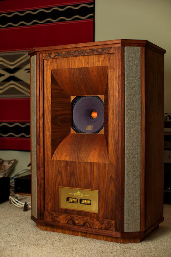
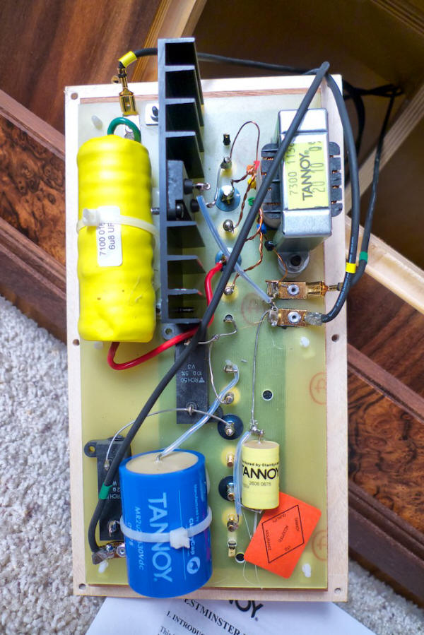
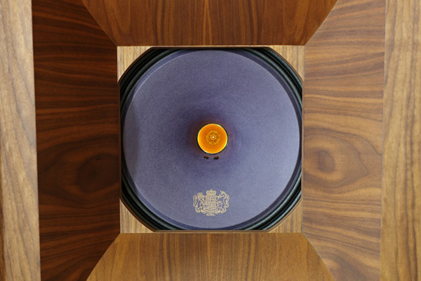
A number of events occurred at about the same time that made me feel more confident that it would be possible for me to go forward with the project of upgrading the WRSE crossovers with premium components, the first being when my friend Pete Riggle (Pete Riggle Audio Engineering) said that he'd be glad to lend a little 'roll-up-the-sleeves' sort of help should I be in need of it, and secondly, Pambos said he would be glad to share his insights from doing a number of Westminster Royal crossover upgrades, and thirdly, Mark Coles (Sablon Audio) had lots of great recommendations that would both simplify the WRSE project and further improve the performance, and finally, Dr. Paul Mills, Director of Research & Engineering at Tannoy (and responsible for the design of the latest version of the Westminster Royal SE and the Kingdom Royal) offered to provide advice and guidance as the project proceeded too! Bolstered by the groundswell of support & encouragement, I decided to proceed with the project by upgrading the tweeter capacitors with some premium versions, removing the WRSE internal wiring connectors and then direct soldering the wires, and perhaps to be followed with upgraded inductors and resistors at some point in the future. However, a very special sort of serendipity began to take place as I was discussing the project with Mark Coles (Sablon Audio) when he suggested that he introduce me to his friend Frederik Carøe, the co-founder of Duelund Coherent Audio in Denmark, whose company hand-crafts the beyond state-of-the-art Duelund CAST capacitors, resistors, and inductors. During a very enjoyable discussion with Frederik over the telephone, Frederik informed me that another Positive Feedback Online writer and Westminster Royal enthusiast—the beloved audio luminary Dr. Harvey 'Gizmo' Rosenberg—was the first audio writer to bring the avant-garde audio design work of Steen Duelund to international attention. Both The Doctor and Steen Duelund have since left the planet, but their ideas & writings continue to stir the imaginations of audio enthusiasts and music lovers everywhere. As you get time, I suggest reading through Harvey's articles related to Steen Duelund's design ideas (1, 2) for additional background, as well as those articles by Steen Duelund himself (1). Before The Doctor left the planet, on his blog he talked about how impressed he was with the results of upgrading the components in the crossovers of his Westminster Royal loudspeakers, which you can read more about here. When I told Frederik I was considering upgrading the capacitors in the high-frequency crossovers of my WRSEs, Frederik in essence told me, "Think bigger, MUCH bigger!" and thus the Duelund-Westminster project was born. When Harvey upgraded his Westminster Royals' crossovers, the Duelund CAST components did not yet exist, so Frederik suggested that we create a completely new set of high & low frequency crossovers for the WRSEs using his beyond state-of-art Duelund CAST capacitors, inductors, and resistors, to honor the memory of Steen Duelund and The Doctor, and to see what ultimate level of performance that we might wring from the Westminsters! I thought that Frederik's suggestion was an awesome idea and I am excited to be a part of it! I think The Doctor and Steen Duelund are smiling! Thank you Frederik! Duelund Coherent Audio For those of you who are not yet familiar with Duelund Coherent Audio, I would like to take a moment and acquaint you properly. The principals of Duelund Coherent Audio, Frederik Carøe and Magnus F. Pedersen, started the company about ten years ago based upon their shared friendship with—and education & mentoring from—Steen Duelund. A mathematician by education, a music lover by passion, Steen Duelund's quest for audio perfection inspired Frederik & Magnus to build the highest quality audio components possible without any consideration for cost constraints. All of the Duelund Coherent Audio components are handcrafted using natural materials to the maximum extent possible, because Frederik & Magnus (ala Steen Duelund) believe that natural materials give the optimum reproduction of the recorded music signal. In 2004 Frederik & Magnus researched, developed, and built a new generation of state-of-art capacitors, inductors, and resistors based on Steen's ideas to improve the performance of audio reproduction. In 2005 Steen passed away after a long illness, so he would not get to see their next generation CAST product line of capacitors, inductors, and resistors that Frederik & Magnus released in 2007, in their bid to go beyond the state-of-the-art of what was then considered possible. Frederik & Magnus were satisfied with their effort in developing the CAST components, feeling that they surpassed all of the existing benchmarks within their field, and the CAST components were products worthy of honoring the purist vision of their friend and mentor, Steen Duelund, whose mantra was "to never accept compromise". Frederik & Magnus continue to engage in research and to create new designs for specific or unique applications based upon the knowledge passed on to them from Steen, and in fact one of those new designs was an innovative CAST Mylar 200uF capacitor they developed specifically for the low-frequency crossovers of the WRSEs for the Duelund-Westminster project that are somewhat of a departure from their norm of materials choice—now that's a really cool development that I'll tell you all about in a moment! The Tannoy Westminster Royal SE Crossovers Let's talk about the stock crossovers of the Tannoy WRSE loudspeakers for a moment. In the WRSE loudspeakers with their Dual Concentric™ drivers there are two physically separate passive crossovers in each loudspeaker: a high-frequency crossover located in the lower front of each loudspeaker, and a low-frequency crossover located in the upper back of each loudspeaker. The crossovers are second-order on the low frequencies, and second-order compensated on the high frequencies. The crossovers use Clarity Cap polypropylene capacitors, non-inductive thick film Vishay resistors, very low loss laminated core inductors custom made for Tannoy, and a combination of proprietary high purity silver & Oyaide PCOCC copper hard-wiring. All in all these were very nice component choices. Notably, the WRSE high-frequency crossovers also include treble controls that allow the owner to adjust the high frequency energy and roll-off via an autotransformer in the crossover circuit, so that the high frequencies can be tailored to the owner's room, associated equipment, and personal preferences.
The role of the WRSE's high-frequency crossover—located in the bottom front of the loudspeaker—is to allow the high-frequency information from the music signal to pass through to the high-frequency compression horn driver unit, while filtering out the low-frequency information.
Inversely, the role of the low-frequency crossover—located in the top of the cabinet above the Dual Concentric™ driver—is to allow the low-frequency information from the music signal to pass through to the fifteen-inch direct radiating low frequency driver while filtering out the high frequency information.
The WRSE crossovers use a combination of capacitors, inductors, resistors, and in the case of the high-frequency crossovers—autotransformers—to implement the filtering of the frequencies, to match the two drivers differing efficiencies, and to blend the frequency response of the two drivers into one smooth composite response.
The WRSE crossovers are extremely well designed, so the intent of the Duelund-Westminster project was to re-create the internal Tannoy crossovers' design using the beyond state-of-art Duelund CAST capacitors, resistors, and inductors as external crossovers. The Duelund CAST Copper Foil Paper-In-Oil Capacitors Let's take a look at the Duelund CAST copper foil paper-in-oil capacitors first. I asked Frederik Carøe if he would tell us a little more about their design and what makes them so coveted by the audio cognoscenti.
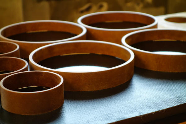
Frederik feels that the Duelund CAST copper foil paper-in-oil capacitors are the ultimate expression of Steen Duelund's thirty-five years of research into perfecting capacitor design for audio use, and as Frederik said, "The legacy of Mr. Duelund is to never accept compromise, and that is a principle we proudly uphold in the Duelund CAST capacitors." Frederik told me that many capacitors today use an insulating plastic film as the dielectric because it makes them inexpensive to produce, but the problem with using plastic is that it noticeably degrades the audio signal, "With plastic you get what Steen would describe as an echo, masking the real details of the signal". So in the Duelund CAST capacitors Frederik doesn't use any plastic, but rather only pure annealed soft copper foil in natural paper and oil, along with resonance control both inside and outside the capacitor. Each Duelund CAST capacitor is completely hand made in an incredibly labor intensive process: "Foils of pure copper or silver are initially wound with paper to a certain value that is a good deal over the needed capacitance. Then the foil is put under vacuum pressure in an oil tank at high temperature for about a week, so that everything inside the winding undergoes vacuum impregnation and is permeated by oil. When this process is done, the resulting foil is wound by hand in a humidity and temperature-controlled room to an exact specification, and then it is placed back into the oil. Immediately after this process the winding is sealed by the use of a special lacquer, which is also used in the yacht industry to seal against moisture. This takes another week."
"During this process a ring of vacuum impregnated paper has been readied with a base of our CAST material. The winding is heated and then placed in the ring & base assembly and CAST material is poured on top of it in five stages, with air bubbles in the CAST material being forced out by applying a very precisely controlled flame to the surface (yes really!). This process takes another week. Following this step the capacitor is measured and checked (as it has been at every step along the way), and if everything is ok, then we ship it to the customer. The total production time is typically six to eight weeks." Other than their obvious high quality, one of the most striking aspects of the Duelund CAST capacitors are their large size and heavy weight, which is due to their perfectionist design using natural materials and pure metal foil—they simply have to be larger than mass produced capacitors with this approach.
Frederik says the careful selection of materials and this no holds barred style of design provides dramatic benefits for audio applications: "From a performance standpoint, the main thing is an absolute lack of coloration, and a much more natural presentation—things don't float around but stay locked in time and space. How you perceive and understand the layers in the music becomes greatly enhanced, primarily because of the sudden silence in between notes. Micro and macro dynamics take on a whole new meaning. Mr. Duelund would liken it to drinking Coke your entire life and then suddenly having a drink of pure water." In the Duelund-Westminster Project we used the copper foil paper-in-oil version of the CAST capacitors, but silver foil paper-in-oil versions of the CAST capacitors are also available should you desire that.
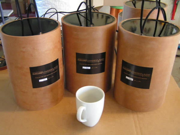
The New Duelund CAST Mylar Capacitors I mentioned earlier in this article that Frederik & Magnus developed an innovative CAST Mylar 200 uF capacitor specifically for the low-frequency crossovers of the WRSEs for the Duelund-Westminster project. The reason they did was because the low-frequency crossovers of the WRSEs have a 200 uF capacitor as part of the circuit, and a 200 uF Duelund CAST copper foil paper-in-oil capacitor would have been of such daunting size that it just wouldn't have been practical for the project. To give you an idea of what I'm talking about, in the photo below you can see some 150 uF Duelund CAST copper foil paper-in-oil capacitors next to a coffee cup for scale—they're huge! Now imagine the even bigger size of 200 uF Duelund CAST copper foil paper-in-oil capacitors—they would be nearly the size of beer kegs!
Creating a Duelund CAST 200 uF capacitor of a more manageable size to use in the C4 position of the WRSE crossovers, while still maintaining a large degree of the performance of the CAST copper foil PIO, became an irresistible challenge for Frederik & Magnus!
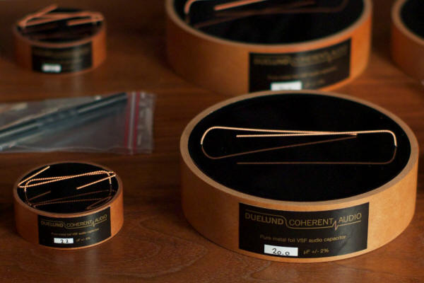
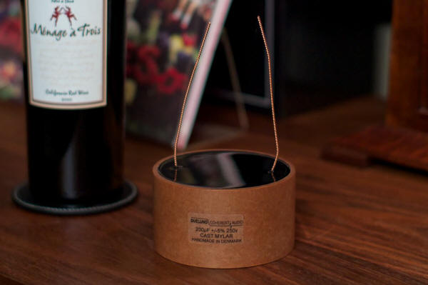
So Frederik & Magnus set to work, and after considering their options, they decided to try using a metalized Mylar foil with the same construction techniques as they use for the premium CAST copper & silver PIO capacitors. Normally Frederik & Magnus would have eschewed the use of a non-natural material like Mylar in one of their Duelund CAST capacitors, instead preferring only pure annealed soft copper or silver foil in natural paper and oil, but as Frederik told me, "The CAST Mylar capacitor is made from four separate Mylar windings. We found that to be the best compromise when size or cost is an issue. The windings are connected to create one 200 uF capacitor. The use of CAST dampening cancels out a lot of typical illnesses in such a design, and we are happy to see them tried in your Westminsters." Below you can see a photo of one of the final Duelund CAST Mylar 200 uF capacitors next to wine bottle for scale, and as you can see, Frederik & Magnus were very successful scaling down the CAST Mylar capacitor's size to be more manageable. While the CAST Mylar may not offer the ultimate performance that the statement copper or silver CAST capacitors offer, it is—as you will find out later in this article—quite remarkable in its own right.
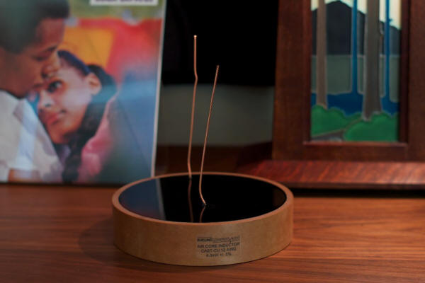
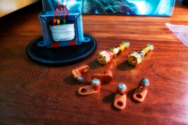
The Duelund CAST Air Core Inductors – A Breath of Fresh Air for Low Frequencies! An inductor (also called a choke) is a passive device that stores energy in its magnetic field (a capacitor stores energy in its electric field). The Duelund CAST Air Core Inductor—as the name implies—utilizes an air core that pure annealed soft copper foil in natural paper and oil is wrapped around (instead of around a magnetic core as with many inductors). A capacitor is made using two foils with paper between the foils, which results in capacitance being created in the electric field between them. An inductor is one foil coiled up. I used the Duelund CAST Air Core Inductors in positions L1 and L2 of the WRSE low-frequency crossovers. The 4.0 mH Duelund CAST Air Core Inductor used in the L1 position of the WRSE low-frequency crossover is shown below.
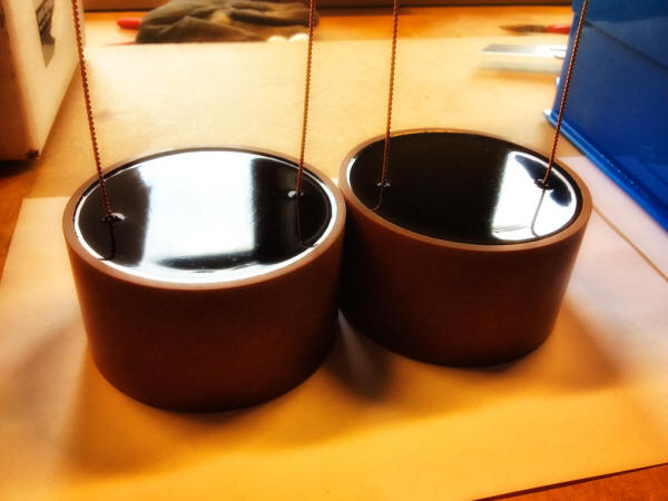
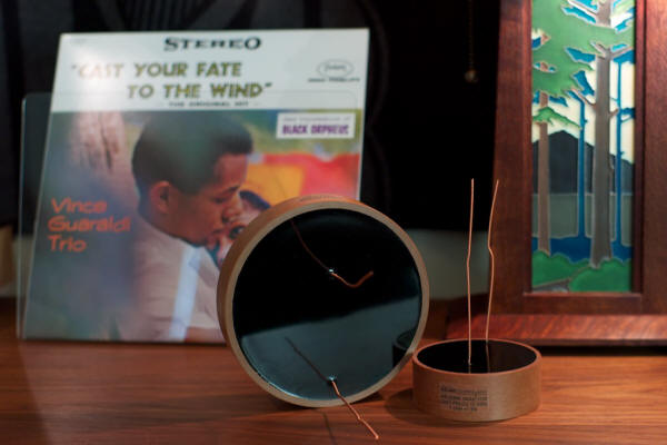
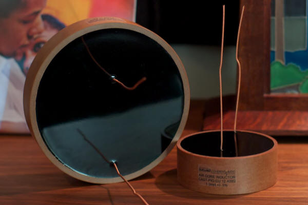
The construction of the Duelund CAST Air Core Inductor is similar to the process used to create the Duelund CAST capacitors, where a foil of pure copper or silver are initially wound with paper around an air core to a certain value of inductance that is greater than the needed inductance. The coiled foil is then put under vacuum pressure in an oil tank at high temperature for about a week to permeate everything with oil. Then the foil is coiled by hand in a humidity and temperature-controlled room to an exact inductance specification, and it is then placed back into the oil. Immediately after this the winding is sealed with a special lacquer that takes a week to cure. During this process a ring of vacuum impregnated paper has been readied with a base of CAST material. The coiled foil is then heated and placed in the ring & base assembly and CAST material is poured on top of it in five stages. A precisely controlled flame is then quickly applied over the surface to drive any air bubbles out of the CAST material. Following this step the inductor is measured and checked against controls to ensure quality. The total production time is typically six to eight weeks to make an inductor. In the photo below you can get an idea of the size of these inductors compared to the LP just behind them—they're huge! The 4.0 mH Duelund CAST Air Core Inductor (position L1 in the low-frequency crossover) is shown on the left sitting on end, and the 1.0 mH Duelund CAST Air Core Inductor (position L2 in the low-frequency crossover) is shown on the right.
Frederick told me, "As far as I know, the Duelund CAST air core inductors are the only paper in oil inductors commercially available to this day." Frederik pointed out to me that many people mistakenly think inductors aren't as important as other circuit components because they typically deal with lower frequencies. He said, "In fact it's the total opposite, the lower registers are far more resonant in nature than high frequencies, which means resonance control becomes even more important. People are always slow to try the inductors, but when they eventually do, they are always amazed at the difference."
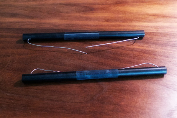
The Duelund CAST Silver / Carbon Resistors In the Duelund-WRSE project I used the Duelund Coherent Audio Silver / Carbon resistors exclusively in the crossover circuits (shown in the photo below).
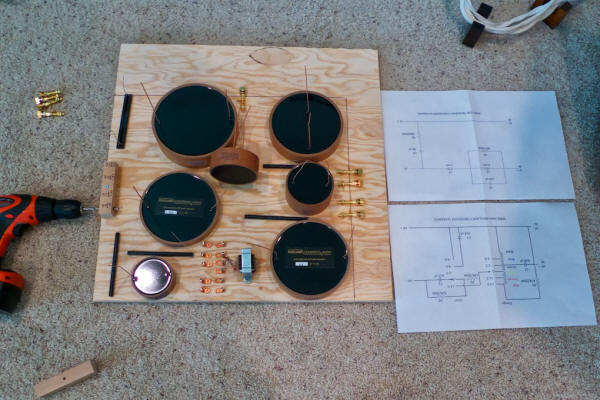
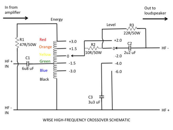
Resistors are inherently simple electrical devices that are used to control the flow of current in a crossover circuit by providing a constant resistance that does not vary with the frequency of the signal, so they are useful for attenuating the signal to match the drivers' needs by consuming excess power and converting it to heat. On the Duelund website Frederik says: "Thus far the resistor has been regarded as a necessary evil, something that was needed out of necessity but scorned for its negative impact on the fidelity of the signal. This has changed with the introduction of the Duelund Coherent Audio Resistors. When designing these components the task was that the voice coil of the speaker and the resistor be viewed as a whole rather than two separate entities. The Duelund CAST process applied to the top of the line resistor makes it an extraordinary component completely without peers. The result is a resistor which seemingly has no sound of its own and it allows the drivers to perform at their very best. Our "humble" opinion is that our resistors are the best "bang for the buck" upgrade available. Simply replace your resistors for unparalled transparency and dynamic ability." I asked Frederik if he could tell us a little about his Duelund Coherent Audio silver / carbon resistors: "The Duelund resistor was created by Steen Duelund, as he found all other resistors fundamentally unsuitable for audio reproduction—being purely industrial by design. It consists of a complete rod with silver lead-outs in a paper tube, which is always made with natural materials, and in the CAST version it is highly damped against resonances. Used in series with a driver, it especially shines, allowing micro and macro-dynamics a full range of expression, unlike any other resistor type." Designing the Duelund-Westminster External Crossovers Caution: If you choose to try and duplicate what I did in the Duelund-WRSE Project with your own loudspeakers, you do so at your own risk, and you are solely responsible for any damage or harm you inflict upon yourself, your loudspeakers, or your domestic relationships. If you burn your house down inadvertently while doing the project, that one's on you too. J Ok, now that I've discussed the three types of Duelund CAST components that will go into the Duelund-Westminster project crossovers (capacitors, inductors, and resistors), let's talk about the crossovers' layout so we can see what goes where. The first thing I did was to sketch out the circuit diagrams for both the high- and low-frequency crossovers, and then I figured out which Duelund CAST component parts I would need (and how many) so I could let Frederik know so he could get started making them. My circuit diagram for the WRSE high-frequency (HF) crossover is below:
For orientation, in the schematic above the signal comes into the HF crossover from the amplifier on the left, and goes out of the HF crossover to the loudspeaker on the right. The list of components needed for one HF crossover are shown below (you'll need to double the amount to build the two HF crossovers you'll need for both your speakers):
Under the 'Energy' portion of the schematic is the autotransformer that is used for the treble energy level control. According to Dr. Paul Mills (Director of Research & Engineering at Tannoy), the autotransformer is a very important part of the circuit and cannot be omitted even if you don't plan on using the adjustability it brings to the high frequencies. Under the 'Level' portion of the schematic are the treble roll-off controls, which I'll discuss in detail a little later in the article.
For your own Duelund-WRSE Project, you'll probably just want to use the well broken in pair of autotransformers off your original crossover boards, but if not, then you can order a new pair through your local Tannoy dealer. If you don't have a local Tannoy dealer then you can go to the Tannoy Sales & Service page of the Tannoy website and you should be able to track down someone who can get them for you.
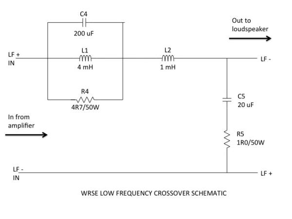
Now lets discuss the low-frequency (LF) crossover: For orientation, in the schematic above, the signal comes into the LF crossover from the amplifier on the left, and goes out of the LF crossover to the loudspeaker on the right. The list of components needed for one LF crossover are shown below (you'll need to double the amount to build the two LF crossovers you'll need for both your WRSE speakers):
A couple of notes about resistors: The stock Tannoy WRSE crossovers use 50W rated resistors (as above), so you might be wondering if it is safe to use the Duelund CAST resistors that are rated at 5 or 10W depending on the resistor. I had the same question so I consulted with Dr. Paul Mills at Tannoy, and he told me the 5 W or 10W Duelund CAST resistors would be fine in all positions, saying "The 50W resistors require a very large heat sink for that rating, and with no heat sink will de-rate to around 10W or less." I have been using the 5W & 10W Duelund CAST Carbon/Silver resistors in my crossovers for some time now, and they have functioned flawlessly, with no signs of being thermally stressed. Also, you should note that the R5 position 1R0/10W resistors in the schematic are not a standard Duelund CAST resistor value, so you'll need to use a pair of 2R0/10W Duelund CAST resistors in parallel to achieve the 1R0/10W value in the R5 position of each LF crossover. Once I had worked up the full list of components from the schematics, I was able to let Frederik know the full Duelund CAST components count needed for the Duelund-Westminster crossovers so he could start building them (the prices I have included below are the discounted prices listed at Parts Connexion as of September 2013):
As Frederik alluded to, the Duelund CAST components can take quite a while to build, particularly for this size of an order, and depending on how many orders are in the queue at the time you place your order, you should be prepared to be patient, but don't fret, your patience will be rewarded. After I provided Frederik the list of the Duelund CAST components I would need for the WRSE crossovers—towards the end of December—I settled in for the wait for them to arrive. Summary Scope for the Duelund-WRSE Project While I was waiting for the Duelund components to arrive, I put the time to good use, and had discussions with Frederik Carøe (Duelund Coherent Audio), Mark Coles (Sablon Audio), Paul Mills (Tannoy), David Biancosino (Dave Biancosino, Answers in Art), Pete Riggle (Pete Riggle Audio Engineering), and Pambos on how best to implement the Duelund crossovers, to address the internal wiring of the WRSEs, and to pick the best options for other details related to the Duelund-WRSE crossover project. First let me summarize the scope of the Duelund-WRSE Project that we came up with, and then I'll elaborate more as I describe each step of the project as I go along so you can follow along in detail. Essentially the project scope consists of two major pieces: building the Duelund external crossovers, and rewiring and modifying the internals of the Westminster Royal SE loudspeakers. 1. Building the Duelund external crossovers:
2. Internal modifications to the Westminster Royal SE loudspeakers:
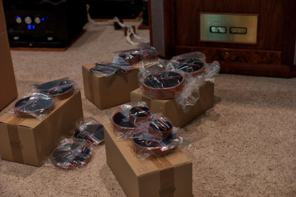
Keeping the high-level project scope in mind, let's proceed with executing the steps of the project. I'll do my best to describe every step of the project in enough detail so that you can figure out how to duplicate the steps for your own project. The Duelund Components Arrive! I received the shipment of Duelund CAST components around the middle of April after letting Frederik know what was needed for the project in December timeframe, although the development of the 200 uF CAST Mylar capacitors did add to the time needed to pull together the full set of components needed.
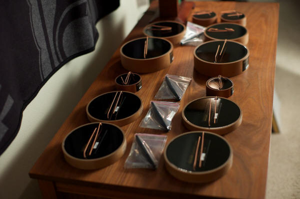
I was stunned when the boxes of Duelund CAST components for the WRSE crossovers arrived (above). I had never seen the Duelund CAST components in person before, and it was quite a sensual treat unpacking them from their shipping containers, holding them in my hands and feeling their substantial mass & size, and if I may say so, admiring the beautiful quality of their construction and their impeccable finish.
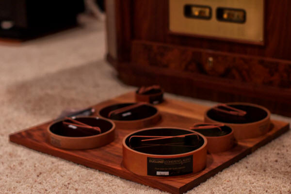
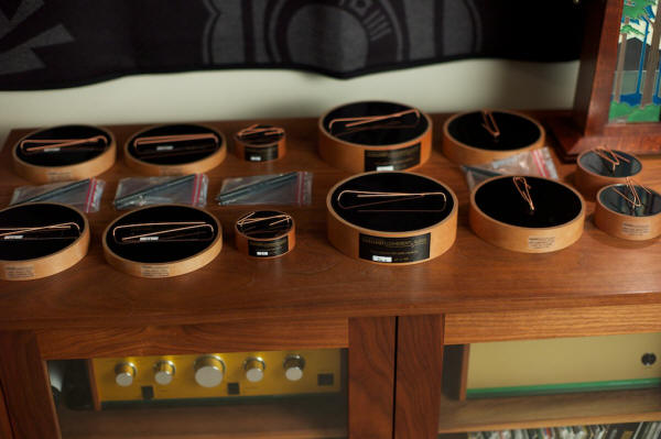
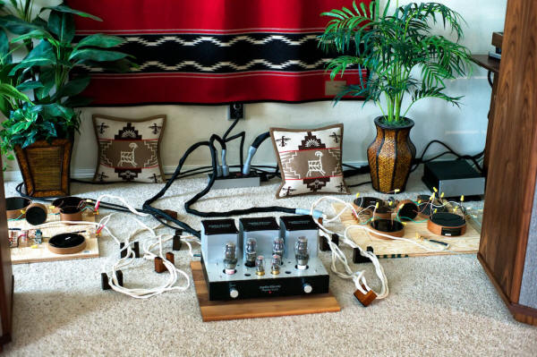
I laid the Duelund CAST components all out on my cabinet—except for 200uF Duelund CAST Mylar capacitors that hadn't arrived yet—for a photo shoot. As a number of my Jeff's Place blog readers and friends have noted, the Duelund CAST components are artistic & attractive in their own right, something that you don't expect from capacitors, inductors, and resistors, and I really wanted to the external crossovers to visibly show their artful aspects to visitors to my listening room—they really are something to behold.
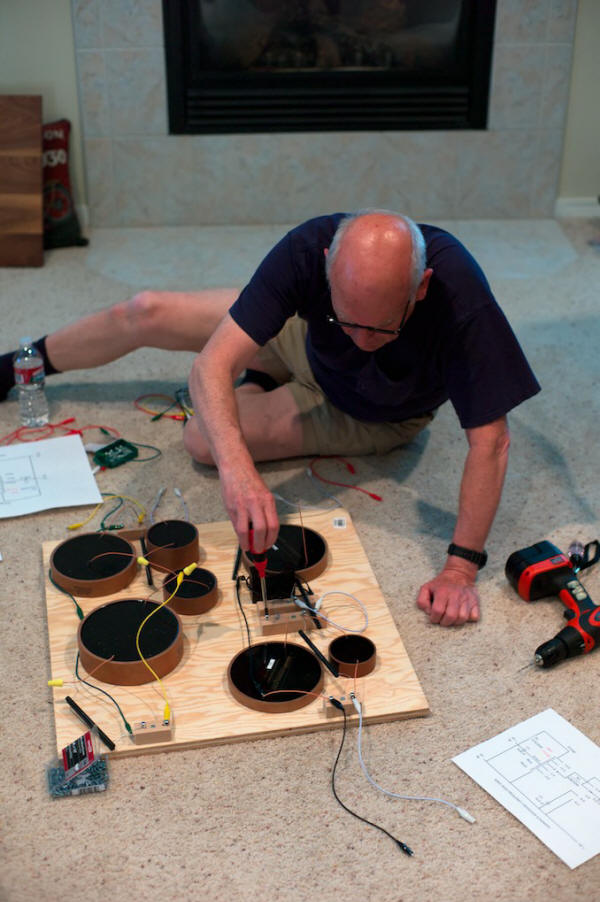
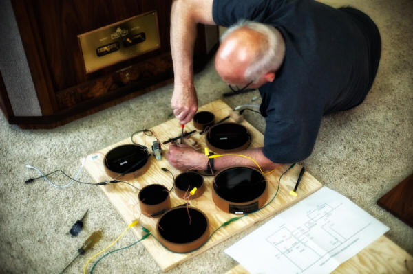
Breadboarding the Duelund External Crossovers The breadboarding of the Duelund external crossovers proceeded according to the following steps: 1. Build a left-channel high & low-frequency crossover breadboard using color-coded Elenco alligator clip leads to help visualize how the Duelund components could be positioned and wired together. 2. Rewire the left-channel high & low-frequency crossover breadboard using generic hookup wire and wire nuts, then test the crossover on the WRSE to make sure the circuit worked as expected. 3. Build a right-channel high & low-frequency crossover breadboard using generic hookup wire and wire nuts with further optimization of the placement of the Duelund components. 4. Test the left & right-channel crossovers on the Westminster Royal SEs to make sure the circuits worked correctly. Well you can only do so much planning, and now having most of the parts in hand, it was time to layout the Duelund external crossovers. The first step was to blow up the crossover schematics to actual 'Duelund-size' to better visualize how to lay out the components, which was the easy way to see how the components for the circuits might best fit together on the breadboards. Audio pals Pete Riggle and Stephaen Harrell, who have done a number of external crossover projects for their own loudspeakers, came by to help me breadboard the left-channel Duelund-WRSE high & low-frequency crossover, then once I was sure I understood what was going on with the circuits, I would take it from there. Thanks to Pete & Stephaen for helping me get off to a good start! To serve as the base for the breadboards we used 2-foot squares of plywood to give us plenty of room. At this point we were not trying to make things pretty, we just wanted to make sure we understood the circuits and how all the components went together. Here's Pete doing some basic layout according to the schematic (below).
I decided I wanted to leave the original crossovers intact and in place in my Westminster Royal SE loudspeakers—but out of the circuit—in case I ever wanted to restore my West's to original condition. That meant I needed a pair of Tannoy autotransformers to complete the Duelund-WRSE high-frequency crossover circuit, which Dr. Paul Mills graciously provided to use for the project. Thank you Paul! As I mentioned earlier, if you decide you want to duplicate this project for your own Tannoys, you'll probably just want to use the autoformers off your original crossover boards, but if not, then you can order a pair through your local Tannoy dealer. If you don't have a local Tannoy dealer then go to the Tannoy Sales & Service page of the Tannoy website, and you should be able to track down someone who can get them for you. Just as an aside: Pambos, Paul, and myself discussed the possible benefits of using autotransformers with silver windings and nickel cores. It is something we'd all like to try, but at this point in time getting special sets of autotransformers made up was a little bit too daunting of a challenge to do in time for the project. Perhaps in the future I'll be able to follow up on that idea, and if so, then I'll report back on the results.
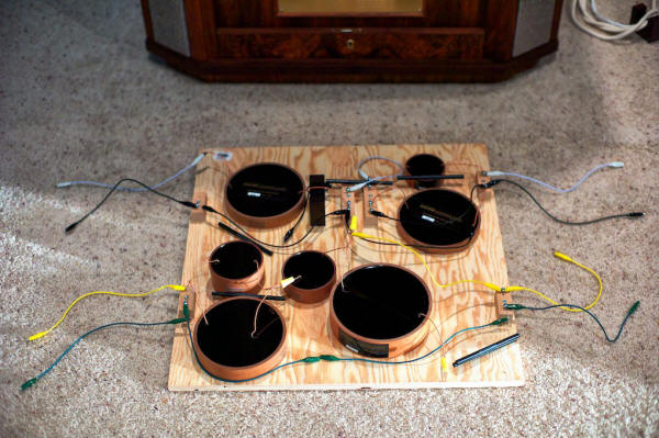
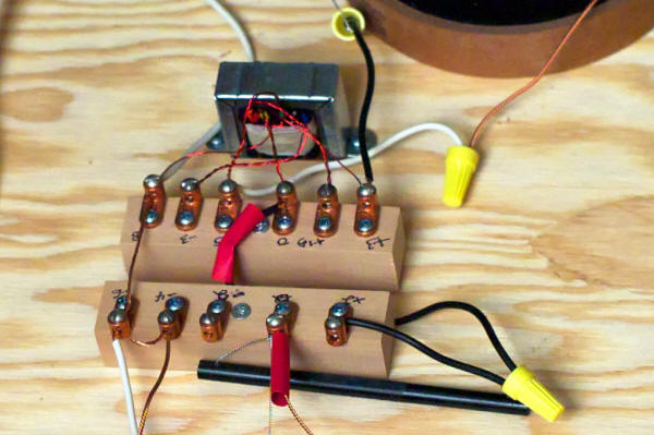
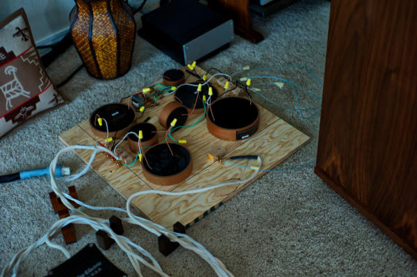
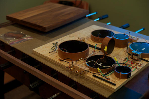
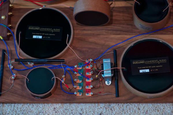
You'll notice that the autotransformer is missing from the parts selection in the photo above, as Paul was so busy getting everything ready for his upcoming Munich Hi-Fi show at the time, he didn't have a chance to get a set of autoformers shipped out yet, but we knew how big they were so we were still able to do a basic layout. In the top half of the breadboard you can see the components laid out according to the high-frequency crossover schematic. An Acoustic Revive cable riser was pressed into service as a mock autotransformer for the purpose of laying out the breadboard until Paul's autotransformers showed up (they're about the same size). In the upper left of the breadboard the white Elenco alligator clip lead represents the HF+ IN from the amplifier, and the black Elenco Alligator clip lead represents the HF- IN from the amplifier. On the upper right side of the breadboard you'll notice that white Elenco alligator clip lead represents the HF- OUT to the loudspeaker, and the black Elenco Alligator clip lead represents the HF+ OUT to the loudspeaker. In the bottom half of the breadboard you can see the components laid out according to the low-frequency crossover schematic. On the bottom left side of the breadboard the green Elenco alligator clip lead represents the LF- IN from the amplifier, and the yellow Elenco alligator clip lead represents the LF+ IN from the amplifier. On the bottom right of the breadboard the green Elenco alligator clip lead represents the LF+ OUT to the loudspeaker, and the yellow Elenco alligator clip lead represents the LF- OUT to the loudspeaker. The color-coded Elenco alligator clip leads were only used to help visualize how the crossovers would be wired together, and of course they were not used in the final design. I ordered a couple of sets of the Elenco TL-6 Standard Alligator 10-Piece Lead Set from Amazon.com at $5.77 each, and they turned out to be really handy for visualizing how the Duelund components were to be wired together on the crossover, and to determine what lengths of Neotech wire would be needed for the final wiring of the crossovers. Once the Tannoy autotransformers arrived from Paul we got busy putting them in place on the breadboard (below).
At this point we also began to rewire the left-channel high & low frequency breadboard crossover using generic hookup wire and wire nuts, readying it for eventual testing on the loudspeaker to make sure the circuit was working as expected.
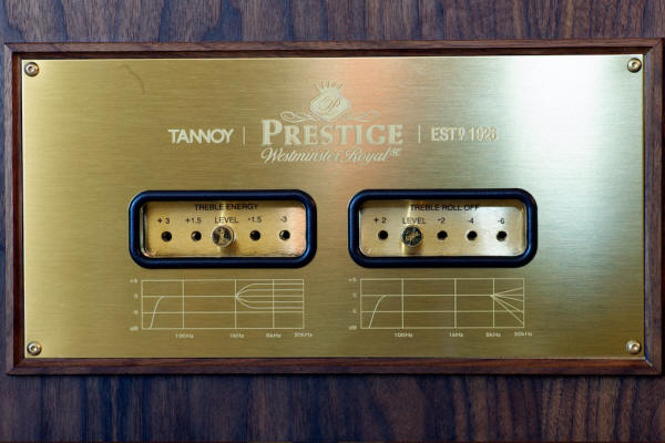
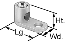
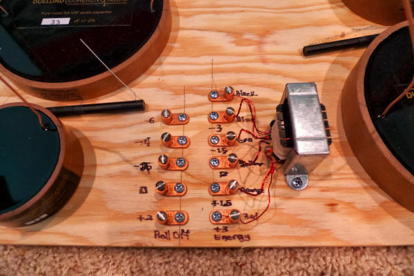
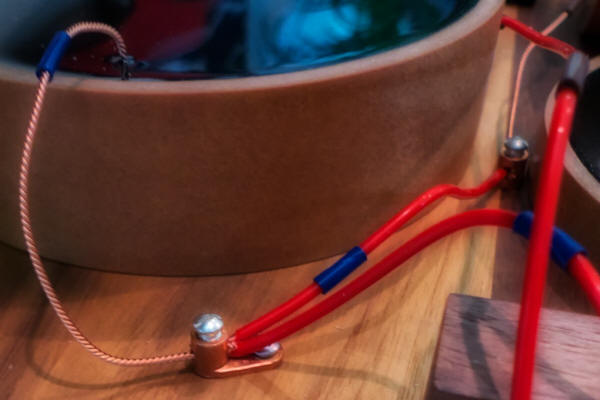
I wanted to maintain the adjustability (treble energy level controls & treble roll-off level controls) of the high frequency section of the crossover that is normally located on the front panel of the WRSE (photo above), so we relocated it to the outboard crossover, laying it out according to the high-frequency circuit schematic. We used copper setscrew lugs for direct wire-on-wire connections so there's zero performance loss as compared with the stock adjustors. Wire-on-wire connections are better sounding than having the additional materials of intervening connectors that the signal has to go through. Pete recommended that we use straight-tongue copper setscrew lugs, 14-8 AWG, #10 stud, from McMaster-Carr, part number 6923K61.
Above is a close-up of the breadboard version of the treble energy & treble roll-off level controls for the high frequency section of the crossover. With this design I have to move the two lead wires with the red heat shrink around on the setscrew lugs to change the treble energy & treble roll-off settings, but maintaining the purity of the signal more than makes up for the nuisance of having to loosen a screw and move a wire.
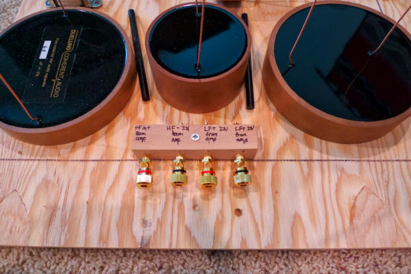
Binding Post Bypass Method: One of Mark Coles' suggestions was to use the binding post bypass method for connecting the speaker cables from the amplifiers to the crossovers, and the internal cables from the WRSEs to the crossovers. With the binding post bypass method, the binding posts are not in the circuit, they're just used to clamp wires together from the crossover to the cables from the WRSE & the amplifiers, eliminating another potential signal degrading connector material from the signal path. With the binding post bypass strategy, each crossover required 4 pairs of binding posts, or a total of 8 for both channels. You don't need fancy binding posts with this strategy, as they're not in the circuit, they're just used as a clamp to clamp wires and cables together. I bought 10 pairs (2 spares) of the Dayton Audio BPA-38G HD Binding Posts from Parts Express at $7.94/pair.
It's a little hard to see in the photo above, but the bare wires from the crossover go through the binding posts, and then the spade connecters from the amplifier speaker cables or the WRSEs' internal cables are clamped directly to the wires, eliminating the signal degrading binding posts from the circuits. There are better close-up photos later in the article of the final design so you can see the details. Testing the Left-Channel Breadboard Crossover: While unorthodox, it was actually quite illuminating to test/hear the left-channel Duelund breadboard external crossover while listening to the stock Tannoy right channel internal crossover at the same time. It was like listening to two different loudspeakers as a stereo pair, and then trying to characterize what the difference was between the two loudspeakers. The good news was that the test was a success—the left-channel Duelund breadboard crossover was functioning perfectly!
My first impressions were this: Oh my God—what a difference! In the most general sense, all the things that I know and love about my Westminster Royal SEs were intact, but enhanced to a remarkable degree. With the Duelund components the inherent voicing of the WRSE was retained, which is what I was hoping for, but the performance level was rather dramatically increased. It's always a little bit exciting/scary for me when I first fire up a system after having performed some modifications, not knowing for sure if there will be some unanticipated operational mishaps. When I first fired up the system to warm up, everything seemed to be ok, so I walked over to listen to the stock right channel WRSE, and then walked over to listen to the Duelund'd left channel WRSE. My heart sank—I couldn't hear anything coming from the WRSE's Dual-Concentric driver in the left channel. I assumed there was a loose connection somewhere, so I put on an album and thought I'd jiggle wires until I figured out where it was. To my surprise music came out of both channels of the WRSEs, the Duelund HF & LF crossover was just so much quieter than the stock Tannoy HF & LF crossovers that I thought it wasn't working, but it was—it was just very quiet with no music playing. I told Frederik about this result and he told me: "I'm thrilled by your description. The silence is my main thing, as this really makes the music exist. Without silence there can be no detail. What you are hearing is the lack of resonance that was present in the old crossover, meaning that the speakers were never silent and never controlled." All I can say is that I was floored by the difference between the two crossovers, with the Duelund breadboard crossover being so quiet. The reduced noise level that results from the choice of materials and the resonance control of the CAST process that Frederik & Magnus use in creating the Duelund components works amazingly well, that's for sure. On the Duelund crossover'd WRSE side of the room there was a massive increase in the sense of recorded space and room ambience, which I suspect was contributed to greatly by the CAST inductors of the Duelund LF crossover. There was also a dramatic increase in transparency. The soundstage really opened up with something like double the depth, more natural height, and a very distinct layering of images back into the recesses of the soundstage. The images were solidly and naturally presented, with a lush sense of ambience and space around them. The stock Tannoy crossover sounded two-dimensional and opaque in comparison to the Duelund crossover. It was a bit weird hearing this major positive transformation of the sound & musicality from the Duelund breadboard crossover on the left side of the room, while the right side of the room sounded… well not so good in comparison. I wouldn't characterize the stock WRSEs as a bad sounding speaker—far from it! They are amazingly musical instruments as loudspeakers! However, with the Duelund breadboard crossover in place on my left channel Westminster Royal SE, it gave me a sense of what the WRSE loudspeaker was truly capable of, and it made me terribly excited to get on with the project. As I said, the Duelund side was very quiet from a background noise standpoint. Particularly on good recordings, until an instrument comes in you almost think its not working, and then magically the instrument fills the room with music. The presentation of the music was also much more natural and relaxed sounding with the Duelund crossovers, and it felt more like music, if you understand what I mean. The stock Tannoy crossovers are harsh & edgy sounding in comparison, although I would never have characterized them that way had I not heard the Duelund crossovers, which sound so utterly natural and musical. What the left-channel Duelund breadboard crossover did for the sonics and musicality of my Westminster Royal SE was quite impressive, because with the Duelund breadboard crossover in place there was a whole level of information that came through my West' in terms of highlighting shades of tonal colors (more about this below), musically natural timbral detail, emotive qualities, and important and relevant sonic & musical information that just wasn't there before with the stock crossover—it really is a big deal! With the Duelund breadboard crossover there was also less sense of strain on dynamic peaks, and the dynamic contrasts across the dynamic range from softest to loudest were more discernable. Dynamic transitions to crescendos, decrescendos or diminuendos became revelatory with the Duelund bread crossover. The Duelund crossover's side also played louder without any harshness. It was a bit weird feeling my right ear starting to shut down on the stock Tannoy crossovers at a certain level of loudness, while the left ear was relatively unfazed and relaxed on the Duelund side. I wouldn't have thought that could happen, but it did. Ok, those were some of my first impressions for you from the left channel Duelund breadboard crossover test, and I'll have a lot more to say about the sonic & musical attributes of the Duelund crossovers as this article progresses. With a successful test of the left-channel Duelund breadboard crossover complete, I was more than a little excited about getting the right-channel Duelund breadboard crossover up and running!
In the right-channel breadboard I wanted to implement the following lessons learned from the left-channel:
With this in mind I laid everything out on the second piece of plywood breadboard (below).
The two plywood breadboards for the left & right-channel are the same size (2-feet by 2-feet), but with a little careful positioning I was able to save quite a bit of space (the black lines show the new more compact size, compared to the original dimensions of the left-channel breadboard). The space inside the black lines is 18.5 inches by 20.5 inches, which is the same size as the vibrational energy dissipation platforms walnut top plate, which was my size goal.
I also eliminated the mounting blocks for the treble energy & treble roll-off controls to mount the setscrew lugs directly to the breadboard (above).
Instead of using two separate blocks for mounting the HF & LF binding posts I used one block (above). So when all was said and done, I had a complete right-channel Duelund breadboard crossover incorporating the lessons learned from the left-channel crossover (below).
The final step in the breadboarding process was testing the left & right-channel Duelund breadboard crossovers on the Westminster Royal SEs to make sure the circuits are working correctly.
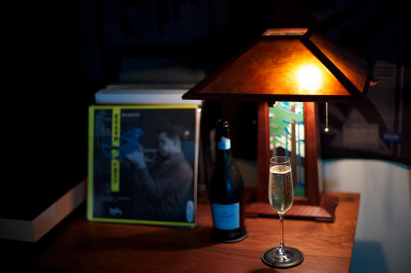
I was really excited by the results I got when testing the left-channel Duelund crossover, so I was really looking forward to testing both channels with the Duelund breadboard crossovers. The results were pretty much what I was hoping for, with the right channel Duelund crossover functioning perfectly as well, and adding the benefits I heard from the left channel breadboard Duelund crossover to the right channel Westminster Royal SE loudspeaker. I thought the performance transformation of my Westminster Royal SEs was breathtaking, and that was without any run-in time on the Duelund breadboard crossovers! Here's a snippet from my listening notes recorded at the time: "I'm sitting here listening to a new Chet Baker Quartet LP (photo below) I bought from Acoustic Sounds (Barclay Disques label) that is sounding so good it's blowing my mind. Just before this I had my Analogue Productions test pressing LP of Bill Evans' Waltz for Debby spinning on the 'table and it was blowing my mind too. Ok that's it for now, and I'm declaring today a complete success."
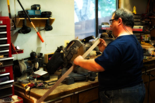
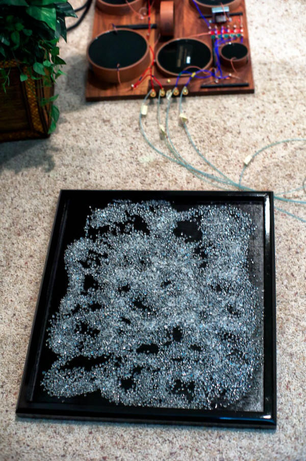
I was so pleased with the resulting improvement in performance to my beloved Westminster Royal SE loudspeakers from adding the Duelund CAST breadboard crossovers that I popped the cork on a bottle of Champagne to celebrate and took the rest of the evening off to listen to music and enjoy the fruit of my labors! The Final Version of the Duelund CAST External Crossovers Once the breadboarding of the Duelund CAST external crossovers was complete, I began building the final versions according to the following steps: 1. Build the vibrational energy dissipation platforms to mount the Duelund CAST crossovers on. 2. Install the Duelund CAST components and Tannoy autotransformers from the breadboards onto the vibrational energy dissipation platforms. 3. Use straight tongue copper setscrew lugs from McMaster-Carr for mechanical connections of the wires on the crossover boards. 4. Use 20-gauge Neotech solid-core UP-OCC silver wire with a Teflon jacket to wire the high-frequency section of the crossover. 5. Use 14-gauge Neotech solid-core UP-OCC copper wire with a Teflon jacket to wire the low-frequency section of the crossover. The inspiration for the final chassis design for the Duelund CAST external crossovers came from the creatively brilliant Mr. Ken Ishiguro of Acoustic Revive fame, whose innovative applications of physics, materials science, and audio engineering principles to his high-performance Acoustic Revive audio products never fail to amaze me in their cleverness and effectiveness in enhancing the performance of my audio system. I chose to base the chassis for the Duelund CAST crossovers on concepts related to the Acoustic Revive RST-38 Quartz Under-Boards I reviewed in Chapter 7 of The Acoustic Revive Chronicles, which are my favorite audio stands/platforms. As I described them in the review, the Acoustic Revive RST-38 Under-Boards are stands, or more correctly, vibrational energy dissipation platforms, to place your audio equipment upon. The RST-38 Under-Boards are designed to quickly route vibrational energy away from audio components and dissipate it. They feature a composite wood chassis that is filled with quartz granules, upon which a birch plywood top plate is placed to sit components upon. The idea behind using quartz fill in the chassis of the RST-38 Under-Boards is to harness the piezoelectric properties of quartz to dissipate vibrational energy, thereby improving the sound of Hi-Fi electronics placed upon them. Acoustic Revive says that vibrational energy from a component travels through the top board to the quartz filling where it is dissipated, and conversely that vibrational energy coming up through the floor or equipment into the Under-Board's chassis is also transferred to the quartz and dissipated. I would have built the Duelund crossovers directly onto the RST-38s if they were big enough, but they weren't. The massive size of the Duelund components means that I needed the bases for the crossovers to be 20.5-inches by 18.5-inches, and the RST-38′s 17-inches by 13-inches was just too small to accommodate the king-sized Duelund CAST components. My friend and colleague, Dave (Dave Biancosino, Answers in Art), who is also an expert woodworker, helped me develop and build the final chassis for the outboard Duelund CAST crossovers. After we had the basic design planned out we went into Dave's woodworking shop to get the chassis started.
Instead of the composite wood chassis and birch plywood top plate of the RST-38, for the Duelund crossovers I wanted to try a tonewood approach (tonewoods are woods used to construct musical instruments, which I thought was quite fitting in this case): a maple frame with a birch ply base, and a solid walnut top plate.
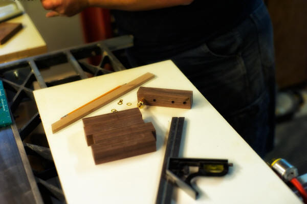
In the above photo you can see the Duelund breadboard crossover in the foreground, and the walnut top plates in the background. The first thing Dave did was to make the terminal blocks that the binding posts would be mounted to (below), which would then be attached to the walnut top plates.
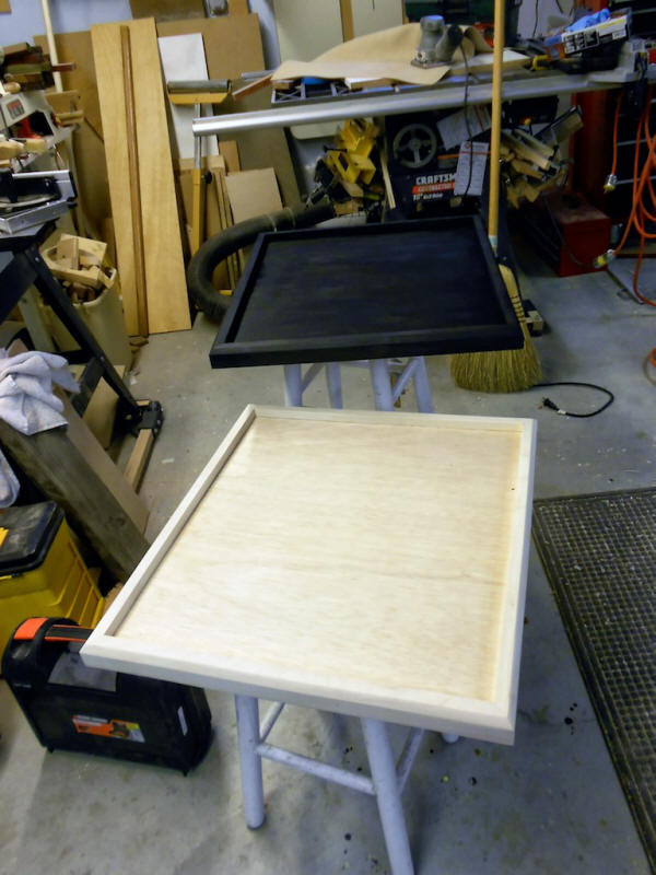
Then we got started on building the maple frames to fit the dimensions of the 18.5-inches by 20.5-inches walnut top plates, which gave us the needed room for mounting the king-sized Duelund components. Dave thought it would look nice to use a black ink stain on the maple frames to give the isolation platforms a complimentary finish to that of the Duelund CAST components, which I thought was a particularly cool idea. After Dave did the glue-up and sanding of the frames, he used an India ink dye to stain the wood. Dave said, "Although any stain or dye would work, to get a jet black finish, India ink or a black acrylic would be needed. The acrylic would not show the grain as well, however." After Dave did the dyeing with the India ink, he did a light sanding because the ink is water based and will raise the grain a bit. Dave chose a clear gloss wipe-on polyurethane finish and put 6 coats on the frame. Dave lightly sanded between each coat with progressively finer paper each time to give a beautifully smooth finish. Dave told me, "Although the bottom will not be seen, it's important to at least put a coat or two of finish on it as well to eliminate the possibility of warping. You want moisture content of the wood to be the same throughout the wood." In the foreground below is the unfinished maple frame mounted on the plywood base, with the stained (but without the final finish steps) maple frame on the plywood base in the background.
While Dave was completing the finish work on the maple bases, I installed the walnut binding post blocks onto the walnut top plates, and then got busy mounting the Duelund CAST components.
Since the layout was optimized on the breadboards, all I really had to do was transfer over the Duelund CAST components to the walnut top plates. To mount the Duelund CAST components to the walnut top plates, Pete recommended that we use straight tongue copper set screw lugs, 14-8 AWG, #10 stud, from McMaster-Carr, part number 6923K61 (I ended up using 21 of them in each crossover to complete all the wire-on-wire connections, for a total of 42, at $1.83/each USD).
The wire leads from the Duelund CAST components were inserted directly into the setscrew lugs and clamped together to give the best possible connection.
For the wiring within the crossover itself, Mark Coles recommended that I use 20 gauge Neotech solid-core UP-OCC silver wire with a Teflon jacket for the high-frequency section of the crossover (I used approximately 12 feet—6 feet per crossover—at $21.34 USD per foot), and 14 gauge Neotech solid-core UP-OCC copper wire with a Teflon jacket for the low-frequency section of the crossover (I used slightly less than 16 feet—8 feet per crossover—at $5.95 USD per foot).
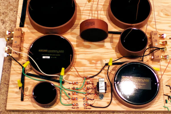
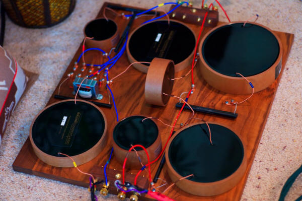
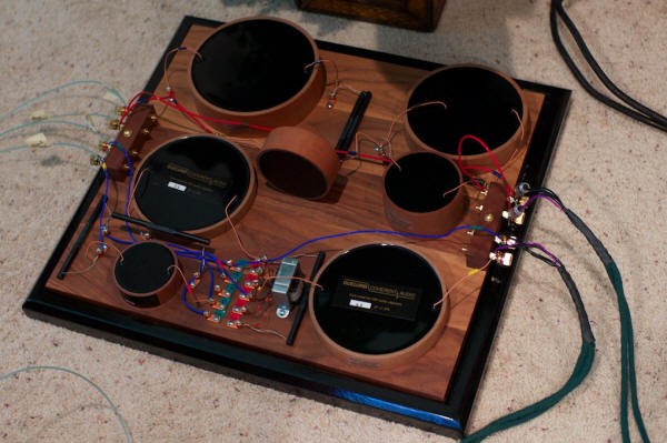
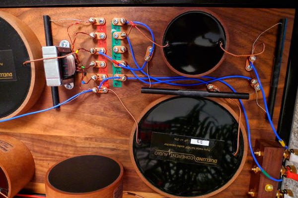
You can see the blue Neotech silver wire used in the adjustable high-frequency portion of the Duelund CAST crossover (above), and the red Neotech copper wire used in the low-frequency crossover in the photo below, now with all of the Duelund CAST components installed on the walnut top plate.
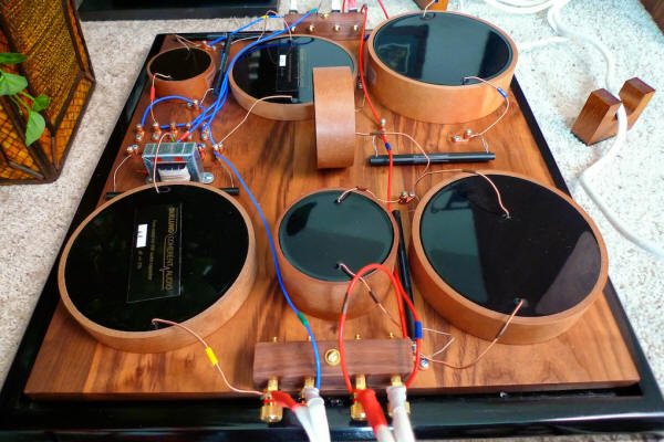
When I got the finished frames from Dave I placed the quartz granules in the bases and placed the walnut top plates into the bases, and voilà—the Duelund-Westminster CAST external crossovers were born!
A breaking news note about isolation platforms: While it will be too late coming for inclusion as part of this article, the nice people at Soundcoat Company, who have been providing specialized noise control solutions to aerospace, medical, and industrial applications since 1963, have been working with me to integrate cutting edge vibration-control technologies into the Duelund-WRSE Project isolation stands in a number of clever and easily applied ways, both by providing vibration reduction technologies for the entire stand, as well as for each of the Duelund components mounted upon them. Additionally, the Soundcoat Company will provide additional vibration control technologies that can be applied to individual components like turntables, phono equalizers, USB DACs, preamplifiers, amplifiers, and other audio applications. I will follow up in a future article to let you know the outcomes of this collaboration with Soundcoat Company on applying their vibration control technologies to audio applications. It's an exciting topic!
A Walk-Through of the Duelund High-Frequency Crossover Let's take a 'walk-through' of the final Duelund-WRSE CAST crossover, starting with the high-frequency section, so you can see in detail how everything goes together in the final design. Below is my high-frequency crossover schematic for a refresher before we start our journey, so hopefully it will help make the photos and discussion a little easier to follow. I'll start at the left side of the schematic where the signal comes in from the amplifier, and then walk my way across towards the right, where the signal goes out to the loudspeaker.
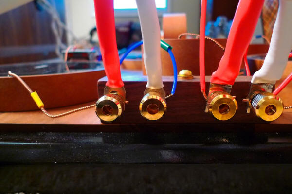
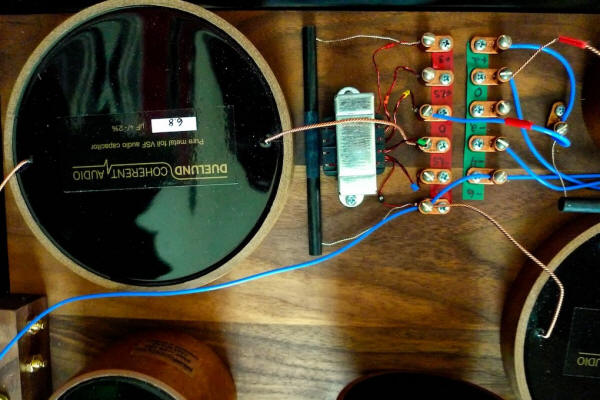
In the photo below you can see the Sablon Audio Panatela speaker cables coming in from the amplifier attached to the HF+ IN (red) and the HF- IN (white) binding posts of the Duelund CAST high-frequency crossover. (The pair of binding posts on the right side go to the Duelund CAST low-frequency crossover, which I'll describe in a moment.)
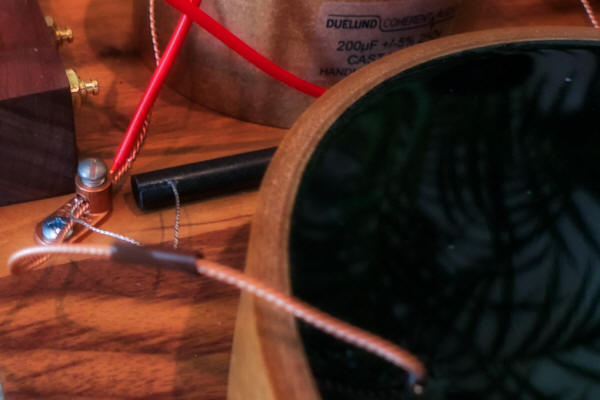
If you look closely at the photo below you can see the details of how the binding post bypass method works for connecting the Panatela speaker cables to the Duelund CAST crossover's internal wiring: The lead from the Duelund 6.8 uF CAST capacitor (C1) inserts into the left binding post's wire passage. The silver spade connector from the positive (red) Panatela cable coming in from the amplifier slips over the binding post shaft directly in front of the wire lead from the Duelund capacitor. When the binding post cap nut is tightened down it clamps the Panatela's spade and the Duelund CAST capacitor lead wire tightly together to make the electrical connection, thus avoiding a signal degrading solder connection, and making for the most direct connection of the speaker cables spade connector possible to the crossover's internal wiring. On the right binding post a 20-gauge Neotech silver wire (blue) is inserted into the right binding post's wire passage. The silver spade connector from the negative (white) Panatela speaker cable coming in from the amplifier slips over the binding post shaft directly in front of the Neotech silver wire lead, and when the binding post cap nut is tightened down it clamps the Panatela's spade and the Neotech silver wire tightly together. As passing the signal through binding posts as part of a circuit degrades the signal somewhat, the binding post bypass method is a truly nice way to get the binding posts out of the circuit and at the same time avoiding an equally signal degrading solder connection! Thanks again to Mark Coles for the idea of using the binding post bypass method of connecting speaker cables to the crossover's internal wiring, it's truly an elegant way to preserve the fidelity of the audio signal passing through the circuit as much as possible.
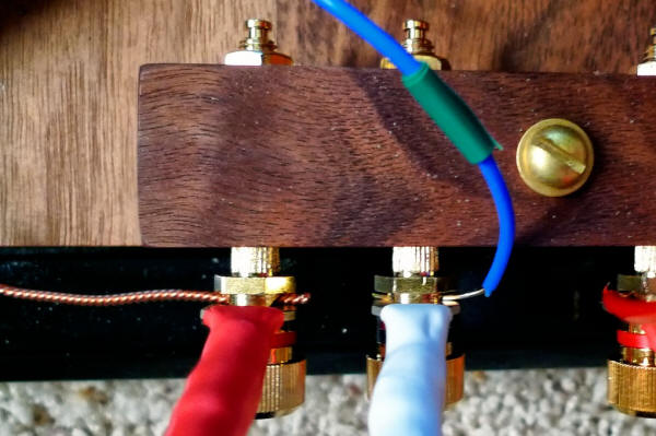
In the photo below you can see the entry lead (with the yellow tape marker) going from the HF+ IN binding post into the C1 Duelund 6.8 uF CAST capacitor, and from the HF- IN binding post you can see the 20-gauge Neotech silver wire (blue wire with green tape marker) going off into the distance to connect at the setscrew lug that connects to the black wire on the autotransformer, the R1 Duelund 47R/5W Carbon/Silver CAST resistor, and the C3 Duelund 3.3 uF CAST capacitor. The copper setscrew lugs serve the same sort of clamping function as the binding posts do in the binding post bypass method, where the setscrew simply clamps the two wires tightly together in the lug for a signal-preserving solder-free connection. To maintain as much signal fidelity as possible, there are absolutely no solder joints used in the Duelund CAST external crossovers. Only the leads from the Duelund CAST components, connected where necessary with the shortest possible lengths of the ultra-quality Neotech hookup wire, make up all the wiring used in the circuits, and all connections are made with the setscrew lugs. Thanks to Pete Riggle for suggesting the idea of using the copper setscrew lugs to connect the Duelund components' leads to the crossovers' internal Neotech wiring, as it's truly a superb way to preserve the fidelity of the audio signal passing through the circuit as much as possible, with the added bonus of being able to quickly change out a component should that be desired.
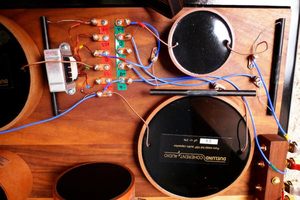
In the photo above you can see the lead from the Duelund 6.8 uF CAST capacitor (C1) inserting into the red-tape side -1.5dB treble energy level setscrew lug where it connects to the green lead of the autotransformer (the 3rd red-side setscrew lug up from the bottom of the photo). The photo above also shows a close-up of the aforementioned 20-gauge Neotech silver wire (blue) coming in from the negative binding post and inserting into the bottom red-tape side setscrew lug that connects the black wire on the autotransformer, the R1 Duelund 47R/5W Carbon/Silver CAST resistor, and the C3 Duelund 3.3 uF CAST capacitor. You can see the R1 Duelund 47R/5W Carbon/Silver CAST resistor positioned between the C1 Duelund 6.8 uF CAST capacitor and the autotransformer. Note that R1 Duelund 47R/5W Carbon/Silver CAST resistor also inserts into the red-side +3dB treble energy level setscrew lug (the top setscrew lug on the red-tape side in the photo below).
As with the stock internal Tannoy WRSE crossover, the Duelund CAST external crossover allows the treble energy level of the tweeter to be adjusted over a range of -3dB to +3dB by selecting different taps on the autotransformer that increase or decrease the tweeter energy level in 1.5dB steps from the crossover point. In the Duelund CAST crossover this is accomplished by moving a jumper wire in the crossover to connect to the appropriate autotransformer tap (from top to bottom in the photo below: the red tap is +3dB, the orange tap is +1.5dB, the yellow tap is +0dB, the green tap -1.5dB, and the blue tap -3dB). In the photo below you can see a length of 20-gauge Neotech silver wire (blue with a red tape marker) that is inserted into the +0dB treble energy level setscrew lug (on the 'red-side') that connects it to the yellow tap (+0dB) from the autotransformer. This is the jumper wire that can be moved between the different red-side setscrew lugs corresponding to the autotransformer taps that adjust the treble energy level of the tweeter. In the photo, the Neotech jumper wire is inserted into the +0dB treble energy level setscrew lug, which means that there is zero alteration of tweeter's treble energy level. As we move to the right in the photo (and schematic), the other end of Neotech movable jumper wire is connected to the R2 Duelund 10R/10W Carbon/Silver CAST resistor (which is the horizontal resistor in the middle of the photo) via a setscrew lug that you can see just to the left of the C2 2.2 uF Duelund CAST capacitor (the capacitor in the upper right of the photo). A length of Neotech silver wire also goes from this setscrew lug to the +2dB treble roll-off control that is at the top of the green tape strip in the photo. A length of 20-gauge Neotech silver wire (blue) goes from the -3dB treble energy level setscrew lug (red side) to the -6dB treble roll-off level setscrew lug (green side), and then all the way to the HF+ OUT binding post that goes out to the loudspeaker, where it is clamped to the silver spade of the positive lead (red) of the internal WRSE Panatela wire (lower right-hand corner of the photo).
The treble roll-off circuitry functions as a variable low pass filter, which I'll explain in more detail in a moment, but first let me describe what it does visually by using the diagrams from the front panel of the WRSE treble controls, which I think will give you more of an intuitive feel for what the circuitry does. If you look at the photo below, the diagram underneath the treble energy level control (the left control) shows that when the different transformer taps are selected the treble energy level is changed in steps over the range of +3dB to -3dB at the crossover point, but the change in dB is linear in response with increasing frequency from the crossover point. In the diagram underneath the treble roll-off level control, you can see that the change in dB response is non-linear with increasing frequency. The treble roll-off control provides an increasingly greater dB change in treble response as a function of increasing frequency in a smooth curve (i.e. dB response 'rolls-off' with increasing frequency).
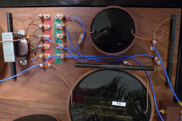
In discussing the treble roll-off control with Paul Mills, he told me that its inclusion in the WRSE's circuit is largely historical in nature, as its original purpose was to tailor the high-frequency response to help reduce the hiss on 78 rpm records. Paul told me that he had considered removing the treble roll-off control from the circuit as it doesn't really serve a useful purpose for modern recordings, but a very enthusiastic core group of Westminster owners who still listen to 78s wanted him to retain it, so he did. Paul advises those not listening to 78s on their Westminsters to ignore the treble roll-off control! Ok, now let's continue our walk across the high-frequency crossover. Take a look at the row of setscrew lugs on the green tape in the photo below—these are the treble roll-off level controls for the Duelund CAST crossover. If you have a lot of 78s to listen to you might want to change the treble roll off setting from the normal +0dB setting to +2dB, -2dB, -4dB, or -6dB to best flatter your particular 78 rpm record.
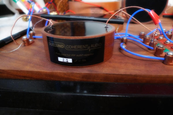
To change the treble roll-off to best complement the 78 rpm record you want to listen to, you would move the lead of the C2 2.2 uF Duelund CAST capacitor (marked with the red tape in the photo) to the setscrew lug with the desired level of roll-off. (It's the capacitor in upper right of the photo above, with a close-up below.)
+2dB setting: If you insert the C2 2.2 uF Duelund CAST capacitor lead into the +2 dB setscrew lug, it places the R2 Duelund 10R/10W Carbon/Silver CAST resistor and the R3 Duelund 22R/10W Carbon/Silver CAST resistor in parallel with the C2 2.2 uF Duelund CAST capacitor to give +2dB of roll-off on its way to HF- OUT. +0dB setting: If you insert the C2 2.2 uF Duelund CAST capacitor lead into the +0 dB setscrew lug, it places the R2 Duelund 10R/10W Carbon/Silver CAST resistor in series with the C2 2.2 uF Duelund CAST capacitor, and the R3 Duelund 22R/10W Carbon/Silver CAST resistor in parallel with the C2 2.2 uF Duelund CAST capacitor, to give +2dB of roll-off on its way to HF- OUT. -2dB setting: If you insert the C2 2.2 uF Duelund CAST capacitor lead into the -2dB setscrew lug, it drops the C2 2.2 uF Duelund CAST capacitor out of the circuit, and the HF+ IN signal from the transformer tap goes through the R2 Duelund 10R/10W Carbon/Silver CAST resistor and the R3 Duelund 22R/10W Carbon/Silver CAST resistor, to give -2dB of roll-off on its way to HF- OUT.
-4dB setting: If you insert the C2 2.2 uF Duelund CAST capacitor lead into the -4dB setscrew lug, the HF+ IN signal from the transformer tap goes through the R2 Duelund 10R/10W Carbon/Silver CAST resistor and the R3 Duelund 22R/10W Carbon/Silver CAST resistor on its way to HF- OUT, and it places the C2 2.2 uF Duelund CAST capacitor and the C3 3.3 uF Duelund CAST capacitor in series across the driver terminals to act as a low pass filter, to give -4dB of roll-off. -6dB setting: If you insert the C2 2.2 uF Duelund CAST capacitor lead into the -6dB setscrew lug, the HF+ IN signal from the transformer tap goes through the R2 Duelund 10R/10W Carbon/Silver CAST resistor and the R3 Duelund 22R/10W Carbon/Silver CAST resistor on its way to HF- OUT, and it places the C2 2.2 uF Duelund CAST capacitor across the driver terminals to act as a low pass filter, to give -6dB of roll-off. Once the incoming signal goes through the treble roll-off level control it ends up at the HF-/HF+ OUT pair of binding posts, which connects to the Panatela internal cabling from the Westminsters using the binding post bypass technique as described earlier (below).
Ok, that's it for the high-frequency section of the Duelund CAST external crossover, so now lets walk through the low-frequency section.
|
|||||||||||||||||||||||||||||||||||||||||||||||||||||||||||||||||||||||||||||||||